General Description
The Evaluation Board demonstrates the RT9427RWSC to provide fuel gauging for single-cell battery packs. The RT9427R reports StateOfCharge, StateOfHealth, FullChargeCapacity, TimeToEmpty and CycleCount. The RT9427R also provides complete battery status monitor with interrupt alarm function. It can alert to host processor actively when condition of battery over/undervoltage, over-temperature in charge/discharge and overcurrent in charge/discharge.
Performance Sepcification Summary
Summary of the RT9427RWSC Evaluation Board performance specificiaiton is provided in Table 1. The ambient temperature is 25°C.
Table 1. RT9427RWSC Evaluation Board Performance Specification Summary
|
Specification
|
Test Conditions
|
Min
|
Typ
|
Max
|
Unit
|
|
Operation Voltage
|
VBAT - VSS
|
2.5
|
--
|
5.5
|
V
|
|
Active Current
|
Active mode, VDD = 3.8V,
BD_PRES_EN = 0 and not including external temp. measurement current.
|
--
|
12
|
20
|
μA
|
|
Sleep Current
|
Sleep mode, VDD = 3.8V,
BD_PRES_EN = 0 and not including external temp. measurement current.
|
--
|
5
|
12
|
μA
|
|
Shutdown Current
|
VBAT = 3.8V, LDO off
|
--
|
1
|
1.5
|
μA
|
|
1.8V LDO
|
|
--
|
1.85
|
--
|
V
|
|
Voltage Measurement Range
|
|
2.5
|
--
|
VBAT
|
V
|
|
Voltage Measurement Error
|
VBAT = 4V
|
-5
|
--
|
5
|
mV
|
|
Sense Resistor Value
|
TA = 25°C
|
--
|
8
|
--
|
mΩ
|
|
Recommended Input Current of Sense Resistor (Note 1)
|
Continuous current at 100% device utilization
|
--
|
--
|
3
|
A
|
|
Continuous current at 10% device utilization
|
--
|
--
|
4
|
|
Peak pulsed current, 250ms maximum pulse width,10% maximum duty cycle, 1% device utilization
|
--
|
--
|
5
|
|
Current Measurement Gain Error
|
(Note 2)
|
-1
|
--
|
1
|
%
|
|
Current Measurement Offset Error
|
|VVBAT - VSRX| = 0V (Note 3)
|
-1
|
--
|
1
|
mA
|
|
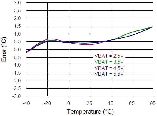
Temperature Measurement Error
|
TA = 0°C to 45°C (Note 4)
|
-1
|
--
|
1
|
°C
|
|
TA = -40°C to 85°C (Note 4)
|
-3
|
--
|
3
|
°C
|
|
Internal Temperature Measurement Range
|
|
-40
|
--
|
85
|
°C
|
|
Internal Temperature
Measurement Error
|
TA = 25°C
|
--
|
±3
|
--
|
°C
|
Note 1. Guaranteed by design and not production tested.
Note 2. Needs firmware compensation parameter applied for temperature coefficient of resistor.
Note 3.Typical result is long time average.
Note 4. The thermistor is uses 10k NTC and beta 3435k, default is SEMITEC 103KT1608T.
Power-up Procedure
Suggestion Required Equipments
- RT9427RWSC Evaluation Board
- DC Power Supply Capable of 6V and 5A
- 1-Series (1sXp) Li-Ion/Li-Polymer Battery Cell
- Electronic Load Capable of 5A
- I2C communication Host
Proper measurement equipment setup and follow the procedure below.
The Evaluation Board is fully assembled and tested. Follow the steps below to verify board operation.
1) Insert battery to battery connector between P+ and P-
2) For discharge, connect electronic load from SRX to P-, adjust the discharge current according to battery spec.
3) For charge, connect DC power supply from SRX to P-, adjust the CV/CC according to battery spec.
4) Get the information like StateOfCharge, StateOfHealth, FullChargeCapacity, TimeToEmpty, CycleCount, Voltage, Current, and Temperature by I2C interface.
Note 5. Contact with RICHTEK for detatiled battery characterizing to get custom parameter for high accuracy StateOfCharge (SOC)report.
Detailed Description of Hardware
Headers Description and Placement
Carefully inspect all the components used in the EVB according to the following Bill of Materials table, and then make sure all the components are undamaged and correctly installed. If there is any missing or damaged component, which may occur during transportation, please contact our distributors or e-mail us at evb_service@richtek.com.
Test Points
The EVB is provided with the test points and pin names listed in the table below.
|
Test Point/
Pin Name
|
Function
|
|
ALERT
|
Alert open-drain indicator output.
|
|
SDA
|
Serial data input. Slave I2C serial communications data line for communication with system. Open-drain I/O.
|
|
SCL
|
Serial cock input. Slave I2C serial communications clock line for communication with system. Open-drain I/O.
|
|
TS
|
Temperature measurement input.
|
|
VSS
|
Device ground.
|
|
V1P8
|
1.8V LDO output. Connect 2.2μF ceramic capacitor to VSS. It cannot provide power for other device in the system.
|
|
VBATS
|
Battery voltage sensing input. Connect to battery positive terminal with kelvin connection.
|
|
SRX
|
Battery current sensing positive input.
|
|
VBAT
|
Power supply input and battery current sensing negative input.
|
|
JB1
|
Battery connector.
|
|
J1
|
I2C communication interface.
|
|
J2
|
Alert pull-high enable.
|
|
J3
|
Load/Charger connector.
|
Bill of Materials
|
Reference
|
Count
|
Part Number
|
Value
|
Description
|
Package
|
Manufacturer
|
|
U1
|
1
|
RT9427RWSC
|
RT9427R
|
Single-Cell
Fuel Gauge
|
WL-CSP-9B 1.68x1.81 (BSC)
|
RICHTEK
|
|
C1
|
1
|
0603B104K500CT
|
0.1µF
|
Capacitor, Ceramic, 25V, X7R
|
0603
|
WALSIN
|
|
C2
|
1
|
0603X105K250CT
|
1µF
|
Capacitor, Ceramic, 25V, X5R
|
0603
|
WALSIN
|
|
C3
|
1
|
GRM188R61A225KE34
|
2.2µF
|
Capacitor, Ceramic, 10V, X5R
|
0603
|
Murata
|
|
RT1
|
1
|
C1608X7R1H104KT
|
10k
|
NTC Resistor, Chip, 3435K, 1%
|
0603
|
SEMITEC
|
|
R1
|
1
|
WR06X4701FTL
|
4.7k
|
Resistor, Chip, 1/10W, 1%
|
0603
|
WALSIN
|
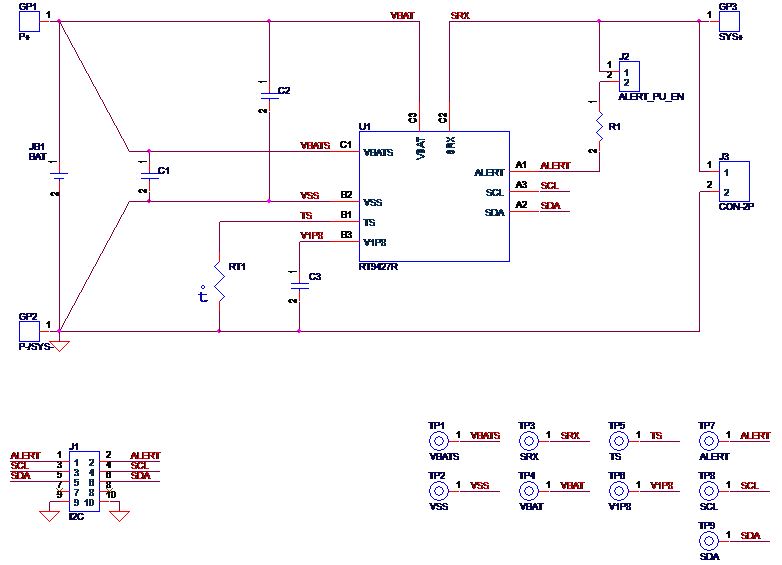
Typical Applications
EVB Schematic Diagram
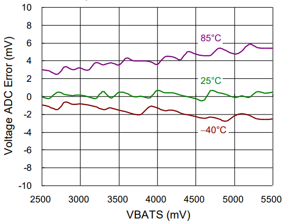
Measure Result
|
Voltage ADC Error vs. Temperature
|
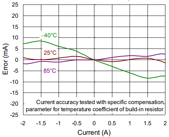
Current ADC Error vs. Temperature
|
|
|
|
|
Temp. Measurement Error vs. Temperature
|
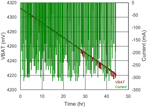
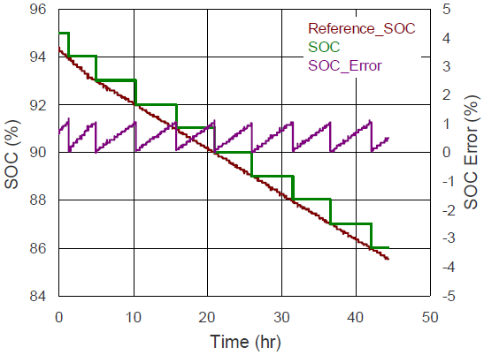
SOC Accuracy*
|
|
|
|
|
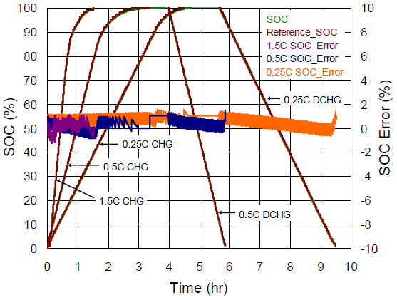
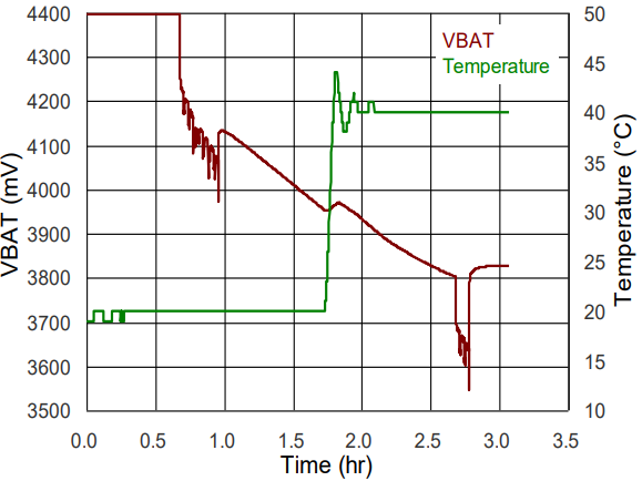
Load / Temperature Transient SOCAccuracy 1/2*
|
Load / Temperature Transient SOC Accuracy 2/2*
|
|
|
|
|
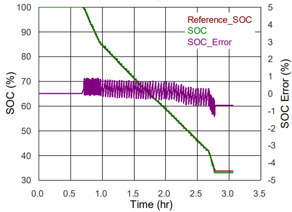
High Pulse Discharge SOC Accuracy 1/2*
|
High Pulse Discharge SOC Accuracy 2/2*
|
|
|
|
*: Sample accuracy with custom parameter into the IC.
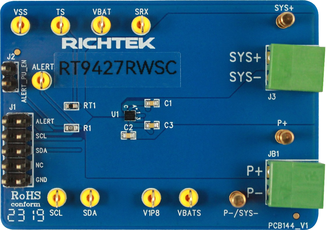
Evaluation Board Layout
Figure 1 and Figure 2 are RT9427RWSC Evaluation Board layout. This board size is 55mm x 40mm and is constructed on two-layer PCB with 1 oz. Cu.
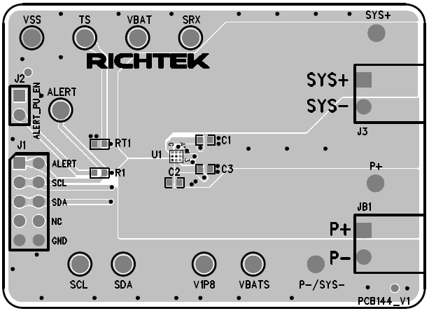
Figure 1. Top View
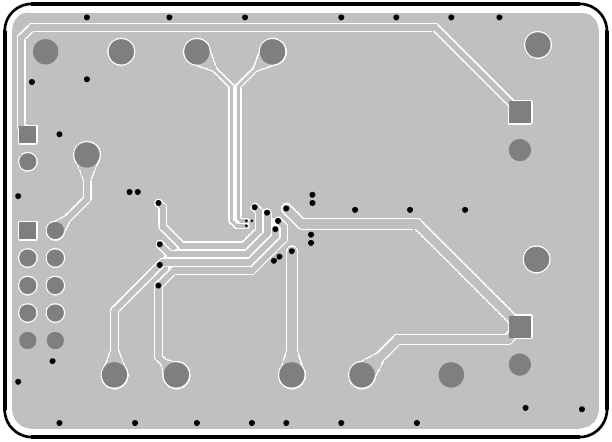
Figure 2. Bottom View